Background
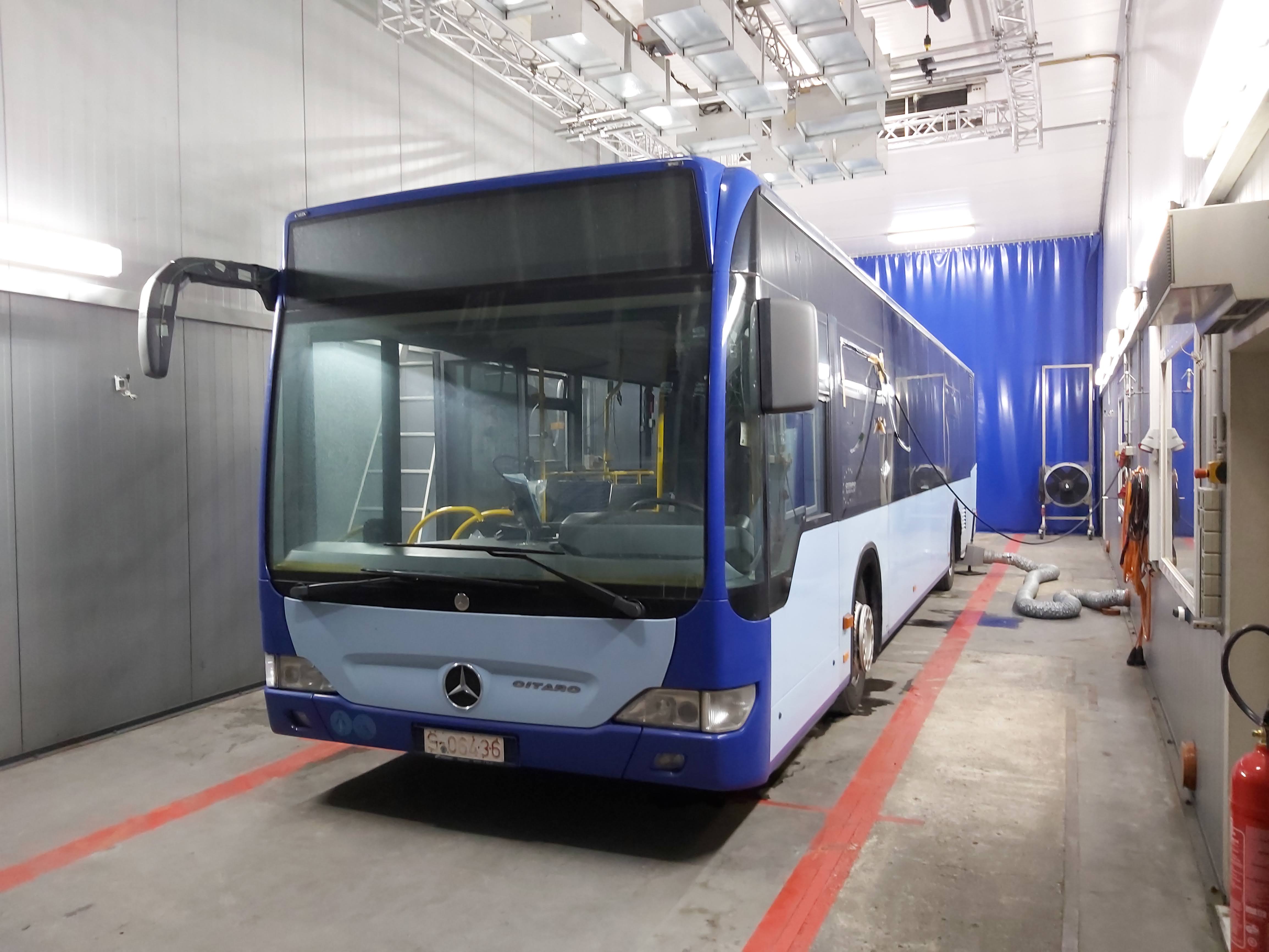
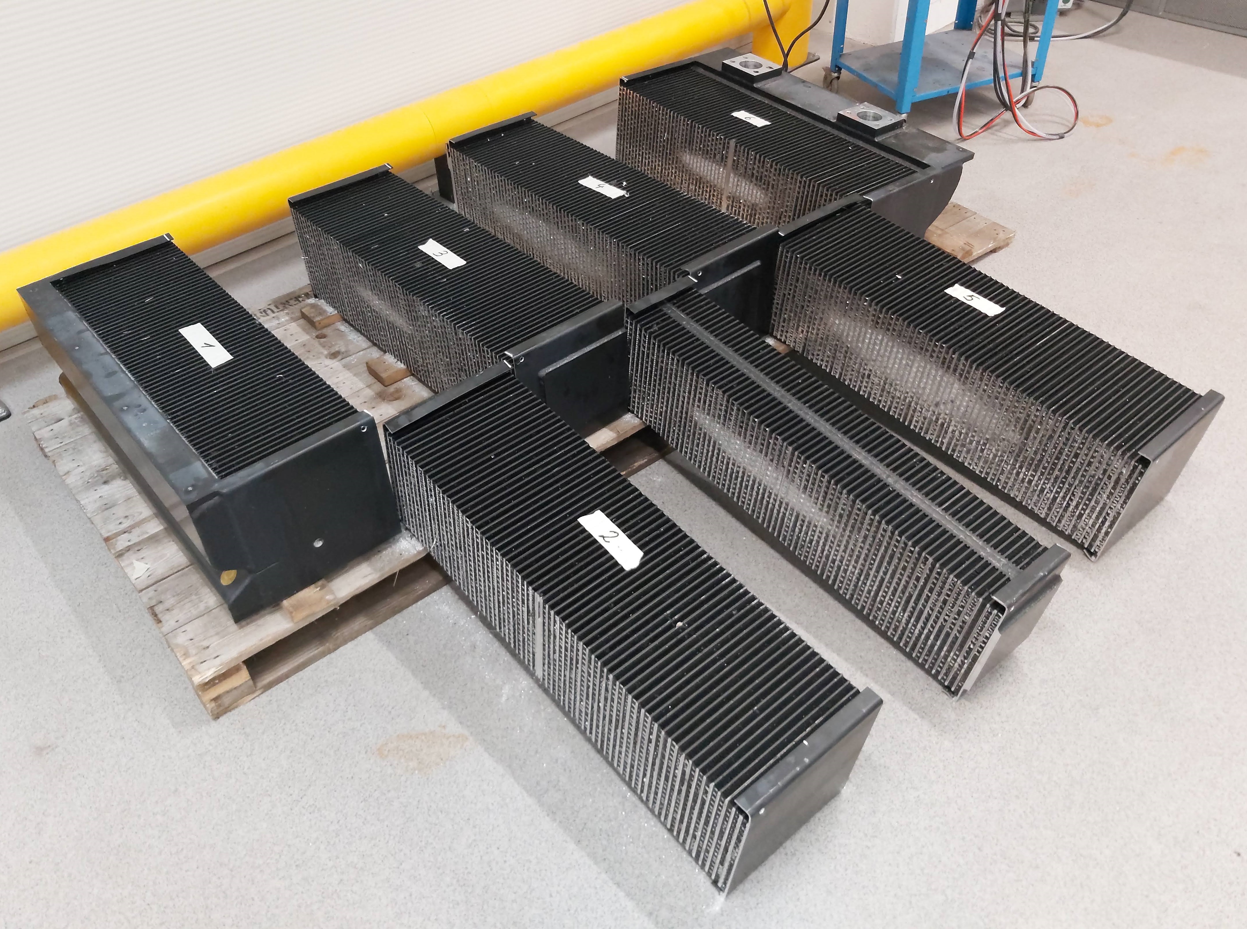
MAHLE produces large aluminum heat exchangers for railway roof-mounted cooling systems. These operate in harsh environments — extreme temperature swings, humidity, UV exposure — making corrosion protection critical.
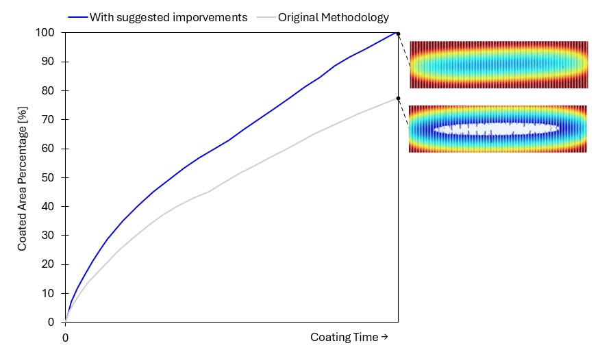
The established epoxy coating method was being replaced by KTL (cathodic dip coating, kathodische Tauchlackierung), which offers significantly better corrosion resistance and is standard in automotive body production. However, applying it to heat exchangers proved far more difficult: the lacquer coated outer surfaces well but left an uncoated ellipsoidal zone deep inside the fin structure.
The Problem
The team had been running physical experiments for months — varying voltage profiles, bath geometry, and anode placement — without a systematic understanding of why the coating was uneven. Each trial cost approximately €2,000 and took weeks to coordinate with external contractors.
One engineer had previously attempted a simulation in COMSOL Multiphysics but stopped after six months without convincing results.
My Approach
Despite initial skepticism from my supervisor, I invested several weekends self-teaching COMSOL Multiphysics and built a first proof-of-concept model.
The model combined several components:
- Parametric 3D geometry of the heat exchanger built in Autodesk Inventor — fin density, dimensions and geometry all adjustable
- KTL bath geometry with configurable anode placement, bath dimensions and heat exchanger position
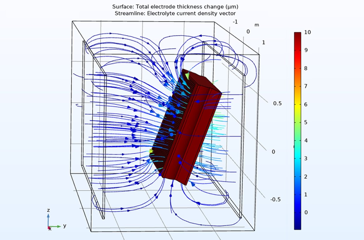
- Iterative deposition model — at each step, the program computed electric field distribution, determined current density at the exchanger surface, deposited a lacquer layer proportional to local current density, then re-computed the field with the now-insulating deposited layer
- Electrical conductivity of both liquid lacquer and deposited lacquer as tunable parameters
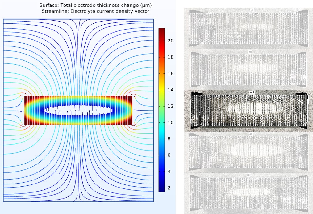
The proof-of-concept immediately reproduced the ellipsoidal uncoated zone — validating the model against physical cross-sections.
Simulation-Driven Process Optimisation
A validated model transformed the way I could explore the process. Instead of expensive physical trials, I could run dozens of virtual experiments in hours — quantitatively studying how voltage, bath size, immersion time, part orientation, and other parameters affect coated area percentage, final layer thickness, and deposition rate. This iterative exploration allowed me to built a deep intuitive understanding of the underlying physics and generate mulitple ideas to eliminate the uncoated zone.
I tested these ideas in simulation — fast, risk-free, and requiring no material or workshop time. The optimised parameter set achieved 23% higher deposition efficiency compared to the standard methodology, and the simulations confirmed the elimination of the ellipsoidal uncoated zone. This opened a new phase of the project with a clear, simulation-backed path to full coating coverage.
Additional Finding: Buoyancy Experiment
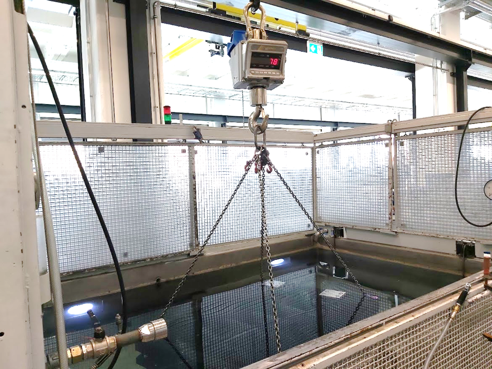
Many contractors had been dismissed because they could not fix the heat exchangers to the bath floor — a requirement assumed necessary to prevent them from floating. I questioned whether the largest exchangers would actually float, given their heavy aluminium frame.
I organised a physical experiment using the workshop crane: a ~500 kg sample was submerged in a water tank with an industrial load cell measuring apparent weight. The result: the largest exchangers generated no net buoyancy — making the floor-fixing requirement unnecessary and reopening access to several previously rejected contractors.
Results
- Model validated against physical experiments — ellipsoidal uncoated zone reproduced accurately
- Paradigm shift from blind trial-and-error to simulation-guided experimentation
- MAHLE purchased a full COMSOL Multiphysics license based on the results
- I trained the remaining team members and documented the methodology before completing the internship
- Buoyancy assumption experimentally disproved — contractor pool expanded